Services

ultrasonic
 

Ultrasonic Thickness Measurement

  • Ultrasonic Thickness Measurement Surveys (U.T.M) on Ship's Hull Structures during
  • Ballast Voyage using Riding Crews Discharge Turnarounds along side Repair Quays in Ports Dry Docks
  • U.T.M for Class Special Surveys (ESP Vessels)
  • U.T.M for Owner's Condition Survey
  • U.T.M for C.A.P Survey
  • U.T.M for Annual / Intermediate Class Surveys
 
structure condition
 

Structure Condition Assessment

  • Renewal planning by indicating condition of steel, higlighting areas of serious wastage, fracturing or buckling based on gauging results, visual inspection & photography
  • Indicating cropping lines for renewal or re-coating and if necessary, calculation of steel weights
  • Providing draft reports at sea during ballast voyage, thus informing Ship Owner in advance, prior to dry-dockling or lay-up.


voyage
 

Voyage Inspection

  • Visual Examinantion and U.T.M gauging of ballasr tanks carried out during ballast voyage using flotation rafts. These methods enable safe access to high-level areas of structure
 
rope access
 

Rope Access

  • Visual Examinantion, N.D.T Inspection and UTM Gauging by Rope Access.
  • Anodes Installation by Rope Access
 
bottompit
 

Bottom Pits Mapping

  • Mapping the extent and severity of individual pits by way od systematically checking corrosion in each bay. The mapping reports will be given in auto cad format and the pit will be measured with pit gauged and ultrasonic meter.


Ultrasonic Flaw Inspection

  • Ultrasonic Inspection is a nondestructive method in which beams of high-frequency sound waves are introduced into materials for the detection of subsurface flaws in the material. The sound waves travel through the material with some attendant loss of energy (attenuation) and are reflected at interfaces (cracks or flaws). The reflected beam is displayed and then analyzed to define the presence and location of flaws or discontinuities.
  • The most commonly used ultrasonic testing technique is pulse echo, where in sound is introduced into a test object and refelctions (echoes) are returned to a receiver from internal imperfections or from the part's geometrical surfaces.
  • Applications include inspections for voids, cracks, and laminations, inspections of welds and thickness measurements.
 
 
magnetic  

Magnetic Particle Inspection

  • Magnetic particle inspection (MPI) is used for the detection of surface and near-surface flaws in ferromagnetic materials. A magnetic field is applied to the specimen, either locally or overall, using a permanent magnet, electromagnet, flexible cables or hand-held prods. If the material is sound, most if the magnetic flux is concentrated below the matrial's surface. However, if a flaw is present, such that it interacts with the magnetic field, the flux is distorted locally and 'leaks' from the surface of the specimen in the region of the flaw. Fine magnetic partcles, applied to the surface of the specimen, are attracted to the area of flux leakage, creating a visible indication of the flaw.
  • The materials commonly used for this purpose are black iron particles and red or yellow iron oxides. In some cases, the iron particles are coated with a fluorescent material enabling them to be viewed under a UV lamp in darkened conditions.


Dye Penetrant Inspection

  • Apart from visual inspection this is probably the oldest and most widely used of all the NDT methods. It can be used on any non-porous material. Its use is confined to the detection of surface breaking defects.
  • Liquid penetration inspection is used to reveal surface breaking flaws by bleedout of a colored or fluorescent dye from the flaw. Test objects are coated with visible or fluorescent dye solution. Excess dye is then removed from the surface, and a developer is applied. The developer acts as blotter, drawing trapped penetrant out of imperfections open to the surface. With visible dyes, vivid color contrasts between the penetrant and developer make "bleedout" easy to see. With fluorescent dyes, ultraviolet light is used to make the bleedout fluoresce brightly, thus allowing imperfections to be readily seen.
  • Penetrant inspection can be used on any material and is most often used on materials clad in stainless steel, and stainless welded items which cannot be inspected by other methods.


Real time “Time of Flight Diffraction Inspection Method” (TOFD)

Our real time TOFD inspection services is an answer to the disadvantages of Ultrasonic Testing by providing real-time permanent scan images with high sensitivity


TOFD Technology is based on the effect of diffraction. Longitudinal wave are used providing full coverage of material between 2 probes. Defects signal is any do appear in addition to 3 reference signals:

 - Lateral Wave (1)
 - Longitudinal wave back echo (2)
 - Mode conversion back echo (3)
 

TOFD Advantages

  • Simple calibration
  • Fast and simple linear scanning
  • 100% raw data recording – second opinion is possible without doing secondary inspection
  • Very sure detection of compact and elongated defects including planar shape and sharp edges defects (cracks)
  • Detection is independent of defect orientation
  • Sizing is not dependent on amplitude of the signal
  • Superior inspection reliability
  • Accurate sizing
  • Reliable propagation monitoring
  • Hard copy evidence
  • Easy storage of data
  • Offline analysis


Alternating Current Field Measurement Inspection Technique (ACFM)

Our ACFM unit has significant advantages over conventional MT and PT techniques. ACFM provides surface and near surface examination without coating removal. It is at least five times faster than the above mentioned conventional techniques providing accurate sizing (length and depth). The soft copy records of the examination display could be used for discontinuity monitoring purposes. This technique adds value with rope access inspection on difficult access areas like crane inspection offshore, platform structural inspection etc.


Advantages

  • Inspection of all electrically conductive materials
  • No coating removal
  • Faster inspection – (Survey from 3mm to 200 mm width in a single pass through up to 8 mm of coating with no requirement to clean back bare metal)
  • Defect sizing – Length & Depth measurements
  • EMA/ACFM/ET/FG modes
  • Battery power
  • Light weight Equipment
  • Full inspection tractability with full inspection data storage and retrieval


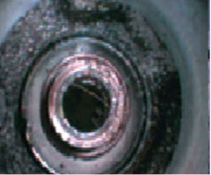
Video Borescope Inspection

Why use Video-scope inspection on any piece of equipment, because as humans, we rely on our visual sense to make critical decision and video-scope inspection lets you visualize what you normally cannot. We don't have to remove or replace the whole pipe/tube if we can inspect the pipe/tube from the inside and fixed the exact location and make the right decision.


There are few advantages of this inspection system

  • Identify possible visualized defect (Poor weld root, pitting, scaling, corrosion, crack, clogging and etc)
  • Observe and categorize the extent of each defect
  • Evaluate turbine/tube/pipe condition and cleanliness
  • Predict possible breakdown of equipment
  • Evaluate the overall condition of equipment
  • Reduce re-piping and re-tubing cost


Radiographic Testing

  • This NDT method is most widely used all over the world. This method uses X or Gamma radiation as probing energy and Film as a recording medium.
  • It is an internal examination method and most sensitive to volumetric defects (Porosity, Slag inclusions). In order to get maximum sensitivity the defect must be parallel to the radiation beam. As the angle between major axis of the planar defect and radiation beam increases the defect sensitivity decreases rapidly.
 
 
  • Radiographic testing is a time consuming process. The exposed film has to be processed in order to decide the acceptability of the part being tested. The cost also relatively high compared to Ultrasonic or Magnetic or Penetrant testing methods.
  • Radiation safety also an important aspect that is always to be addressed according to local statutory : Malaysia Institute of Nuclear and Technology (MINT)


Welding Using Rope Access Method

  • Specialist welding using rope access requires a broad range of skills due to the nature of the service. First technicians need to be highly efficient in Manual Metal Arc Welding. MMAW is the preferred welding discipline due to its high strength when welding structural members & pipework. MMAW is also highly portable. Only requiring the positive leed and welding rods, which reduces set up time in comparison to traditional access systems such as scaffolding.
  • Pipe fitting is usually prepared on the ground before being installed.Then the tie ins are done.Depending on the situation fleeting of the pipe work is require to change out existing pipes.
  • Tig welding can also be performed via rope access when clients require Gas or fuel lines to be installed such as under oil rigs or in power stations. Tig welding on the ropes is usually the hardest to master as the operative needs both hands to perform the weld and the weld quality needs to be of the highest standard.


Painting Using Rope Access Method

  • Proscan Sdn Bhd is the number one rope access company of choice for painting and blasting because we carry out all works quickly and efficiently, to specification and at highly competitive rates
  • Painting and blasting is one of our main rope access activities. We provide trained and skilled painters and blasters plus paint inspectors to ensure the quality of our work is optimal.
  • As a Proscan provider, we are able to support offshore maintenance companies to complete scopes of work and reach areas that could not otherwise be reached using traditional access methods.
  • Having worked on many onshore and offshore projects, we have both the experience and technical capability to carry out client requirements.


Eddy Current Testing of Weld 

  • This procedure defines eddy current examination techniques for detection of surface breaking and near surface planar imperfections, mainly in ferritic material (weld material, heat affected zones, parent materials).
  • This Eddy Current technique can also be applied to other metallic construction materials (e.g stainless steels) if required by the design specification.
  • The technique can be applied to coated and uncoated objects during fabrication and in services, onshore and offshore.
  • The examination can be carried out on all accessible surface and on weld of almost any configuration.
  • This procedure can be applied in the as – welded condition. However, a very rough surface can prevent an efficient examination.


Hardness Testing

  • The testing run on a principle which utilizing impact body of specified weight to bump the testing surface of test piece with a certain test force, then measure the impacting velocity and the rebounding velocity of the impact body respectively when it is 1mm above the testing surface. The Leeb hardness is value is expressed by the ratio of the rebounding velocity to the impacting velocity.
  • Harder materials produce a higher rebound velocity than those which are less hard. With reference to a particular material group, the L-value presents a directs hardness measurement.
Copyright Proscan 2015. All Rights Reserved.